Application scope
Сonducting various seismic survey methods in onshore and offshore wells:
- VSP
- Offset VSP
- MOG, Walkaway VSP
- 3D-VSP
- Cross-Well Seismic Tomography
- Radial VSP
Mechanical and design parameters
| Number of receiver modules in a single downhole string, units | up to 12 |
| Receiver Module dimensions - diameter, mm - length without cable connectors, mm | 51 1050 ± 20 |
| GR module dimensiond - diameter, mm - length without cable connectors, mm - interface unit, mm | 51 530 325 х 280 х 72 |
| Weight: - receiver module, kg - GR module, kg - interface unit, kg - power supply unit, kg | 9 6 4 6 |
| Distance between modules in assembly with cable connectors, m | 4; 10; 20 |
| Diameter of surveyed wells, mm | within 76 – 295 (up to 320 mm when using a 420 mm long clamping arm) |
| Clamping device design | electromechanical type with a DC motor |
| Maximum force at the end of the clamping device arm, kg, not less than | 80 |
| Full opening time of the clamping device, sec, not more than | 40 |
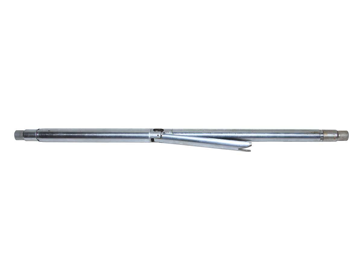
| Seismic receivers assembly design | three-component orthogonal with rigid fixation relative to the module housing |
| Type of seismic receivers used | OMNI-15-1850, OMNI-2400 or equivalent |
Digital and telemetry parameters
| Number of surface channels, including service channels | 8 (up to16 upon additional order) |
| Number of bits for analog-to-digital conversion in downhole modules | 24 delta-sigma |
| Data exchange rate over telemetry line, kbps within the range | from 48 to 120 |
| Seismic receiver unit design | three-component orthogonal |
| Number of seismic channels per module (components: X, Y, Z) | 3 |
| Operating frequency band (at -3 dB level) depending on the sampling period, Hz: 0,125 ms 0,25 ms 0,5 ms 1 ms 2 ms | 3920 1960 980 490 245 |
| Preamplifier gain, dB | 0 – 48 (in 6 dB increments) |
| Instrument noise (on an 1850 Ohm sensor equivalent) depending on sampling period and preamplifier gain, μV, not more than: Td=0,5 ms; Gain=64 Td=0,5 ms; Gain=1 Td=1,0 ms; Gain=64 Td=1,0 ms; Gain=1 Td=2,0 ms; Gain=64 Td=2,0 ms; Gain=1 | 0,190 1,300 0,150 0,900 0,100 0,650 |
| Dynamic range, dB, not less than: - instantaneous (at Gain=1 and Td≥0.5 ms) - considering all gain settings (at Td≥0.5 ms) | 122 139 |
| Permissible limit of the basic relative error of the signal sampling period, % | 0,02 |
| Basic absolute error of time scale synchronization using GLONASS/GPS signals, μs, not more than | 1,0 |
Parameters related to external factors
| Permissible deviation angle of the receiver module from vertical, degrees | 180 |
| Maximum operating pressure for the downhole section, MPa | 100 |
| Operating ambient temperature, °C for the downhole section maximum | +125 |
Downhole equipment components
| Receiver module | 4 units (subject to customer agreement) |
| GR module | 1 unit (upon request |
| Inter-module cable connector | 4 units (subject to customer agreement) |
| Adapter for Ø60mm cable connector | 1 unit |
Surface equipment components
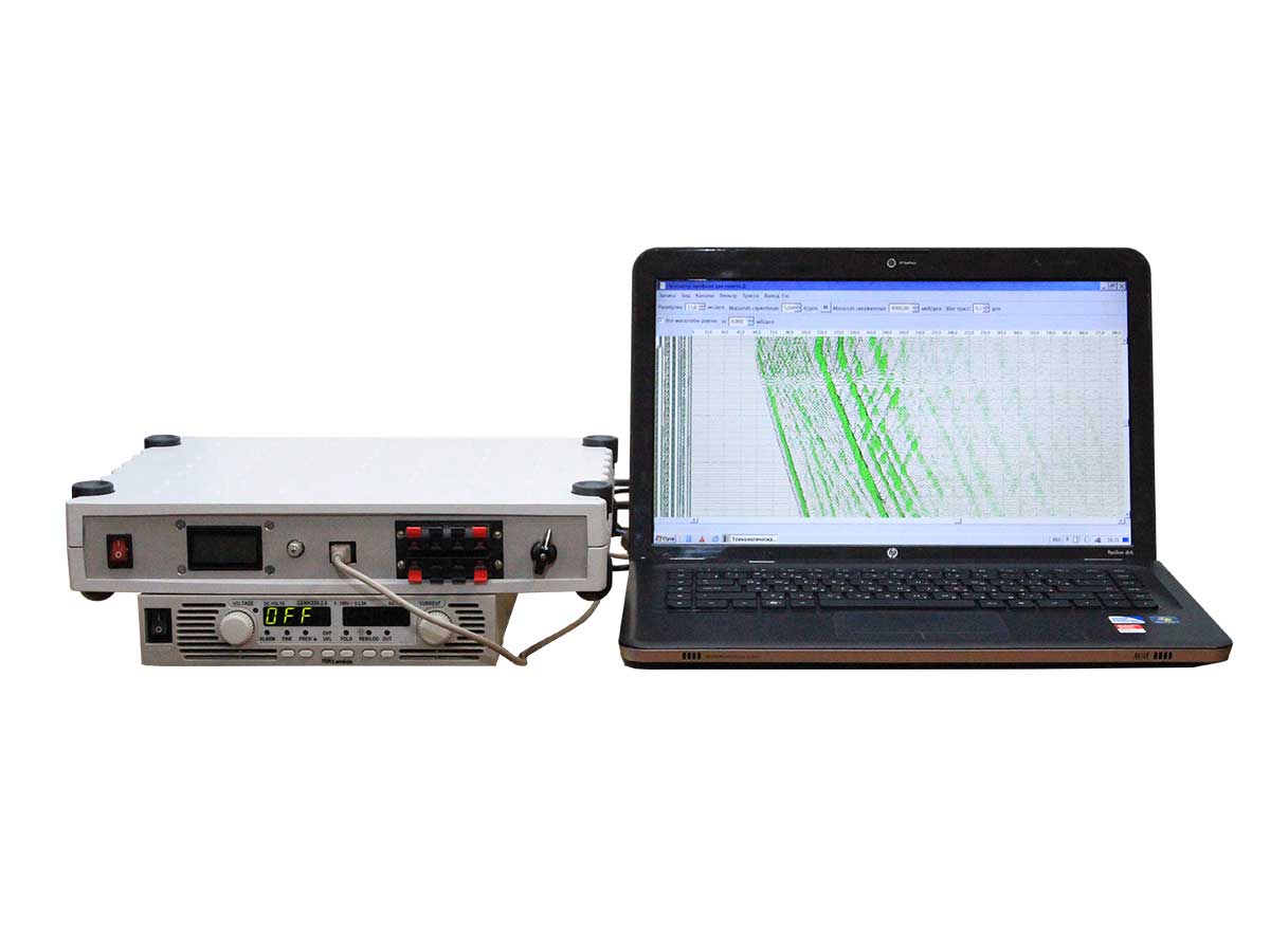
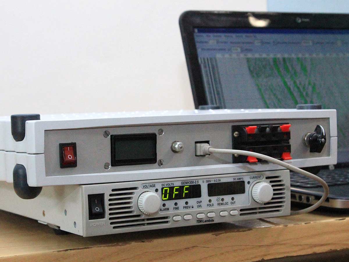
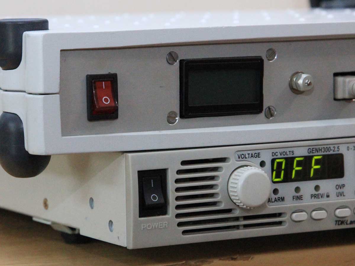
| Interface unit | 1 unit |
| Programmable power supply | 1 unit |
| Computer (Notebook type) | 1 unit |
Technological software
| Technological software installed on the computer | 1 set |
| Backup copy of the technological software on a flash drive | 1 set |
| Special Tool Kit | 1 set (subject to customer agreement) |
| Spare Parts Kit | 1 set (subject to customer agreement) |